Challenge
The project of the OMU (Operation and Maintenance Unit) system was implemented for one of the Polish telecommunications operators. The main task of the developed system was to monitor accuracy of operation and report any technical problems that may occur in devices processing network traffic, for example, in fibre-optic exchanges. As part of the project, apart from the OMU unit, devices, constituting a demonstration set, were made as a complete system, in order to enable the diagnostics of SPF+ and QSFP optical inserts, ventilation control, power supply, temperature reading of individual sections of the device and the status of a redundant power supply.
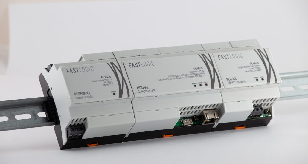
Moreover, the results of the project were demonstration models on which all system components were placed, alongside the XMAN unit. Thanks to this, it was possible to easily make the ready Demonstrator available to the Customer’s engineering team, easily test the functionality of individual devices and conduct tests in a close-to-real environment.
“The OMU project was the first such large-scale telecommunications project carried out at FastLogic. In order to implement it, the documentation and standards for the operation of the SFP+ and QSFP optical and the insert modules had to be carefully read, from the standpoint both of the hardware and the software. One interesting element of the project were the extensive measurements and electrical tests carried out after the devices had started, confirming, among other things, accuracy of the power supply parameters of optical cartridges, the low noise level and the appropriate control sequence in changing environmental conditions.”
Jarosław, Senior Hardware Engineer
The project was implemented in accordance with initial assumptions, regarding the operation and implementation time. The final demonstration unit consisted of 6 modules that were designed, assembled and tested. Each of the elements was equipped with dedicated software that implements the target functionality. Achieving each of the milestones of the project ended with the preparation of appropriate documentation, which included documents such as hardware architecture, software architecture, use cases, user manuals, and communication protocol descriptions. Each element of the project that could have turned out to be problematic had previously been checked, using PoC work, that is, reading data from optical inserts or testing the efficiency of communication channels. Each hardware module was tested and measured in the company’s laboratory and, after completion, reports were then created, with the measurement results then being discussed. All software elements were tested, using prepared test scripts, written in Python. The results of the operation of individual modules were verified with the use of specialised equipment, in that the readings of the parameters of optical inserts were checked with the use of EXFO FTB1.
The devices included in the kit were also tested in ambient temperatures, exceeding 50oC, in order to confirm correct operation under the target conditions.
All electrical and PCB designs worked correctly after the first iteration of the design and, with the minimum of adjustment, they could be used to compile a ready-made demonstration system.
Results & Benefits
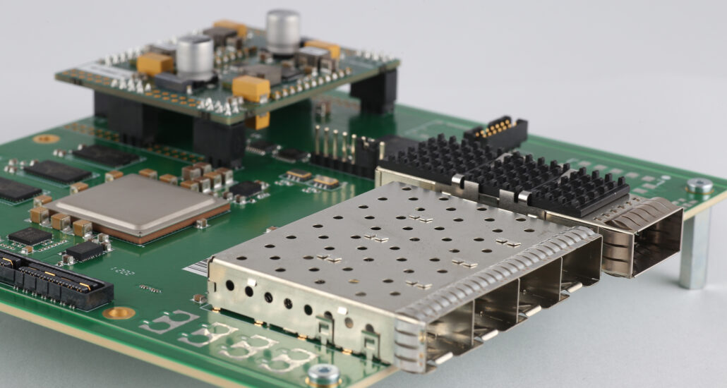
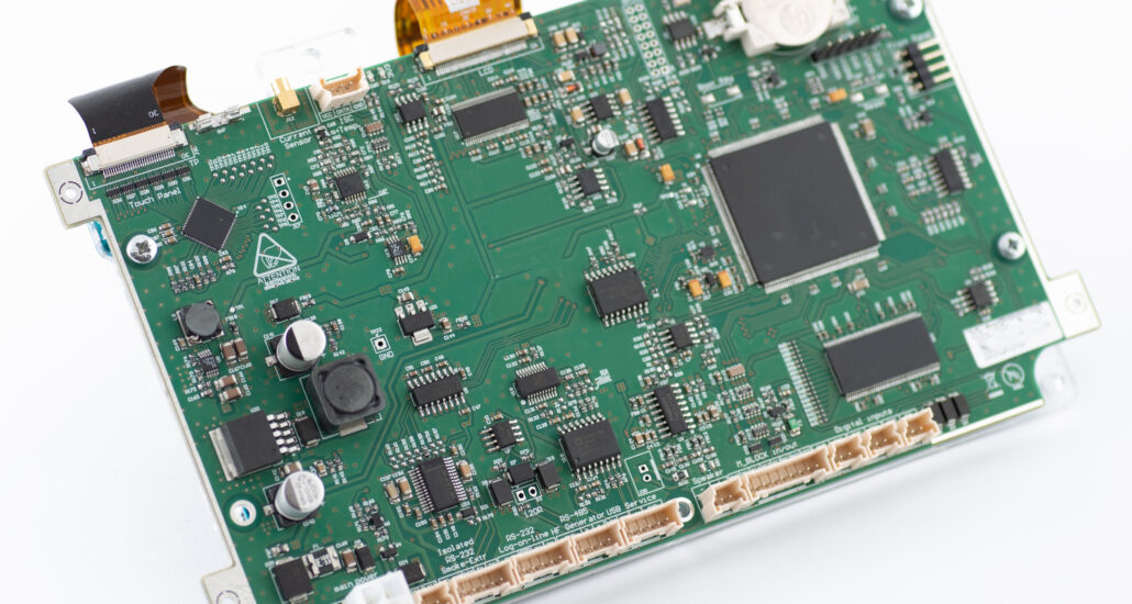
As part of the project, the team developed a functional prototype of the “Operation and Maintenance Unit” device, together with an overlay board for LTE-Cat.4 emergency communication, power distribution boards, fan control boards, and boards that read the parameters of SFP+ inserts (12 pcs per 1 PCB) and QSFP (12 pieces on 1 PCB). Test mock-ups were created and software for all the designed devices and the entire system was integrated into one functioning unit. Electrical and temperature tests were carried out on all boards and their correct operation was confirmed after a few adjustments had been made.
The plates designed:
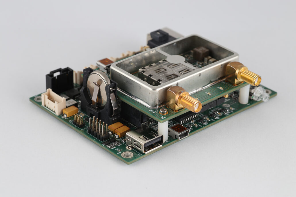
OMU – main unit with CAN, RS485 full duplex and half duplex, Ethernet, SMBus communication interfaces (communication with the redundant power supply); additionally equipped with an ARM-F Renesas processor, an accurate real-time clock and an external watchdog timer. All elements of the device are selected from a series of increased durability and with automotive industry certificates.
- LTE-HEAD – a board that enables backup GSM LTE-Cat. 4. This is an overlay plate, designed to be connected to the OMU board.
- DISTRO – power distribution board with redundant transistor keys and measurement of operating currents and voltages. The board reports any irregularities in terms of voltages and currents to the OMU board.
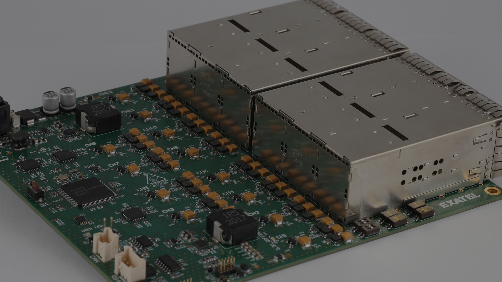
- FANS – a board that controls 8 fan channels, allowing their rotational speeds to be read and any problems to be reported to the OMU.
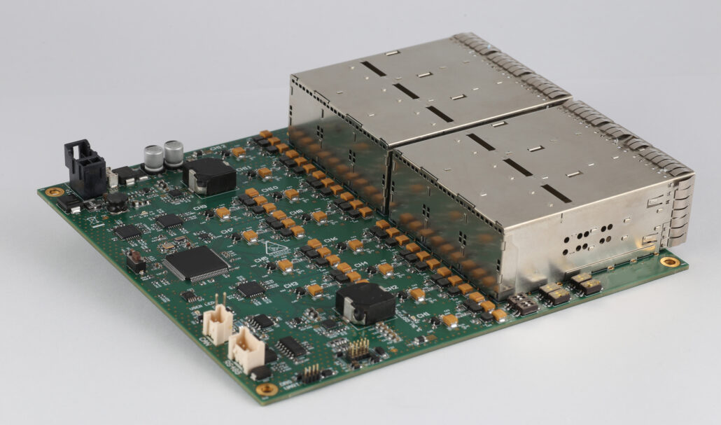
- SFP+ and QSFP – boards that allow fibre optic inserts to be connected and their service parameters to be read; each board has 12 inserts
Key Solutions
- Designing 6 different PCBs,
- Including 5 6-layer boards with impedance control.
- The main device consists of the main board,
- Interconnecting all elements of the entire system and the overlay board realising GSM communication.
Volume and coverage
Research and development project